In QOLO we use shutters mainly for switching between different input signals, such as probe laser and single photons, and for closing individual paths of complex interferometric setups. Typically, there are two methods how to achieve this goal based on mechanical blocking: slow “motorized filter flipper/wheels” and fast “solenoid” shutters. The former are cheap(er), reach the transition time of several hundreds ms and cannot be easily reconfigured for different end-position angles (MFF001, FW102C, 8892-K). The latter can reach sub-ms transition times (over 2 mm wide beam) but they often cause vibrations and excessive heating. For the sake of comparison, the total reaction time is important, not only the transition time. For example, the sub-millisecond shutter SH05 form Thorlabs is characterized by 8 ms time from the application of an energizing voltage to the initial movement of the shutter (Transfer Initialize) and 1 ms time for the shutter to move from 20% exposed to the 80% exposed, measured across the 0.5” travel distance of the shutter (Transfer Open). In reverse direction the times read 13 ms and 1.5 ms, respectively. The SH05 shutter requires a proper driver with quite high holding current, but this is a common feature of all solenoid based shutters. Newport offers models 76992 and 76995 with cca 3 ms total time but the price is higher.
Where sub-ms transition time is required, the optimal solution would probably include voice coil or a solenoid of some kind with a proper driver with the holding current as low as possible (to reduce a heat generated) with very careful mechanical design to remove unwanted vibrations. Robert Scholten maintains an excellent page on this subject. Sub-microsecond pulse durations were achieved using hard-disk voice coil, optimized driver and the shutter V-shaped flag positioned at the focus [R.E. Scholten, Enhanced laser shutter using a hard disk drive voice-coil actuator, Rev. Sci. Instrum. 78 (2) 026101 (2007)]. Unfortunately, the total reaction time is still limited to 4-5 ms (see Figs. 2 and 4 of the previous reference) and the whole device is quite bulky, unless laptop hard-disk is used and reasonably cutted.
For our application, the total reaction or switching time is important, disregarding of how it is distributed between the response of a driver, the transition time of the shutter flag, a jitter of the system etc. Further, we prefer a compact solution with dimensions comparable with a blank pillar post. Here we refer on our shutter solution using digital RC servo. The name comes from “radio-controlled” as these servos are used in remote-controlled models and small-scale robots. RC servo integrates a DC motor (brushless or coreless in case of high-quality servos), gear, position feedback potentiometer, and microprocessor in case of digital servos. Servos are controlled by pulse-width modulated (PWM) signal with typical period of 20 ms, particularly analog servos require repeating (holding) external PWM signal. For digital servos, on the other hand, the single TTL control pulse of given width is sufficient to send the servo to the correct angular position. For example, the digital micro servo SH-0262MG from Savox offers the transition time of 0.06 sec/60 deg @ 6 V and the operating travel of 0-90 deg which corresponds to 1000-2000 us control pulse duration range with the resolution of cca 5 μs (dead band). The SH-0262MG servo employs metal gear but is reasonable small (23 x 12 x 25 mm) and cheap (USD 33). You could certainly find a faster servo (up to 0.03 s/60 deg and 1 μs dead band) but its size would be probably larger and the price considerably higher.

Thin (0.5 mm) metal flag with dimensions cca 5 x 60 mm is attached to the servo shaft. The servo is mounted inside of home-made brass pillar post (external dia 32 mm x height 110 mm) and kept in place by four pieces of Sorbothane sheet so there is no direct mechanical connection between the servo and the post. The end of the servo flag is located in the path of collimated laser beam (cca 2 mm dia) which is then focused on to a photodiode (the lens is placed AFTER the flag). The “on” and “off” positions are chosen to be 85 and 90 deg, respectively, and they are switched periodically with 100 ms delay between them for testing purposes. The oscilloscope trace of the photodiode signal (blue) and the control TTL signal (red) is shown below for ten cycles.

The control signal was generated using Arduino UNO with ATmega328 micro processor by the sketch which follows. The Arduino approach is very convenient, the width of control pulse sent to the servo can be easily set from a personal computer by rs232 communication (the corresponding sketch for Arduino and Python source for PC will be added soon).
int i; int pulsewidth; int angle; int pulseMin = 1000; int pulseMax = 2000; void setup() { pinMode(5, OUTPUT); for (i=0;i<10;i++) { angle=85; pulsewidth = (int)(pulseMin+(float)angle*(pulseMax-pulseMin)/90.0); PORTD |= B00100000; // HIGH delayMicroseconds(pulsewidth); PORTD &= ~B00100000; // LOW delay(100); angle=90; pulsewidth = (int)(pulseMin+(float)angle*(pulseMax-pulseMin)/90.0); PORTD |= B00100000; // HIGH delayMicroseconds(pulsewidth); PORTD &= ~B00100000; // LOW delay(100); } } void loop() { }The servo pinout is: orange – data, red – 5V, black – GND. When driving Arduino through Serial interface, allow for a couple of seconds after opening the serial port. Arduino takes time to initialize. Also, be careful about your variable declarations, signed types, binary structure and parsing.
The detail of “off->on” and “on->off” transition together with the control pulse which triggers the oscilloscope is shown below. Several transitions are captured to show the jitter of our shutter. The photodiode signal responds to the control pulse with a delay of cca 12 ms. The transition time itself is approximately 13 ms and the p2p jitter cca 5 ms. The total reaction time from the leading edge of the control pulse for the open beam to the fully closed regime reaches 6 div, i.e. 30 ms (this “on->off” transition is little bit slower than the “off->on” one, probably due to imperfect alignment of the servo flag vs laser beam).
3D model (Google SketchUp) of the shutter device with digital micro servo in custom brass post with Sorbothane isolation:
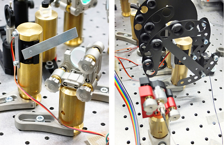
Photos of the shutter and filter wheel using the same digital micro servo:
The servo model employed, the size of the flag and other parameters will be subjects of further optimization. Thermal impact of the shutter will be explored too, as it is crucial for interferometric applications. Suggestions and comments are welcome! Particularly, if you are aware of any application of RC servo for laser shutter, please, post a comment with reference below. Thanks!
Further reading and references
[1] R.E. Scholten, Laser shutter using a hard disk drive voice-coil actuator, School of Physics, University of Melbourne.
[2] L.P. Maguire, S. Szilagyi and R.E. Scholten, High performance laser shutter using a hard disk drive voice-coil actuator, Rev. Sci. Instrum. 75, 3077–3079 (2004).
[3] R.E. Scholten, Enhanced laser shutter using a hard disk drive voice-coil actuator, Rev. Sci. Instrum. 78, 026101 (2007).
[4] M.J. Pritchard, Manipulation of ultracold atoms using magnetic and optical fields, PhD thesis, Department of Physics, University of Durham, 2006. Chapter 8.2.4: Low cost laser shutters.
[5] Description of digital servo features from Futaba.
[6] Online servo database.
[7] Arduino Servo Library, useful mainly for analog servos.


Do you have more details you can share about the filter wheel attachment? Is it threaded for specific filters? The counterweights are brilliant. I just found your pages today and am excited to find others in quantum optics using the arduino in research labs.