In brief:
We often measure voltage in QOLO, that’s why we created a custom four-channel ADC box. There are possible three levels of use – PyQt GUI application, python module in your scripts and commanding arduino anyway you want. Details about electronic connections and some software details are issues are mentioned. Feel free to skip parts you are not interested in.
1. How to
1.0. intended typical application / motivation
In QOLO we need to measure light intensity very often. PIN diode DET36 by Thorlabs produces a photo-current proportional to light intensity. We often use TTi1906 voltmeter to measure this current. The device provides 1 channel with SPS around 2 and requires power cable and a BNC to jack reduction. When reading more currents from one setup, the cables can easily get messy. This was the motivation to use analog to digital converter (ADC). We wanted to build a quick and relatively easy-to-use device for various low-voltage measurements on multiple channels. Typical case is some adjustment measurement that uses DET36 A/M PIN diode connected via variable resistor (because PIN diode is a source of current, not voltage).
1.1. limits
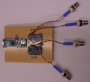
Using I2C bus we connected Adafruit ADS1115 ADC board to a Arduino Micro MCU which we command from python. That yields some limits. One limit is on maximal allowed voltage +/-5V (thanks, Igor). There is a limit on sampling speed (860SPS max) and on serial communication speed (115200 baudrate). Higher SPS modes does not cut-down resolution but increases noise and reduces quality of conversion; details can be found in manual. Presented voltmeter won’t replace oscilloscope but for slowly varying (on scale of to tenth seconds) DC voltages it’s fine. In current implementation using Python program achieved 160SPS when reading single channel and around 200SPS when reading all 4 channels. ADS1115 is 16bit ADC but one bit is a sign bit – theoretically we are able distinguish 2^15 positive voltage levels. Another bad thing is that Arduino Micro has problems with USB3.0 and at least on both Rack computers in QOLO the /dev/ttyACM* port won’t appear.
1.2. the top layer – Python GUI
There is a bunch of scripts in famous and must-have Dropbox spec_and_manuals folder. The most user ‘friendly’ script is called ChannelWindowToolbar.py. It’s a PyQt graphical window that queries the ADC box and draws numbers and graphs in real-time. It can display up to four channels at once. It’s also possible to switch between numbers+graph or numbers only. The window is scale-able and the font-size depends on size of the screen. I use this script when I do fiber-coupling, phase adjusting or visibility measurements. Unfortunately Ubuntu interprets size of the QtWindow the different way than windows on which was the script developed – this is a source of an unpleasant bug – when displaying more channels at once and plotting graphs, the numbers are misplaced.
This is how it looked like on windows XP: http://youtu.be/qhlRKyPTsw8
Source code: https://dl.dropboxusercontent.com/u/99912633/USBBox/Py/ChannelWindowToolbarDev.py
Before using check your port in python script in __init__() method of ChannelWindow object around line 66:
self.det = det("/dev/ttyACM1")
1.3. the middle layer – Python object
Sometimes we need to read values using some script. That’s why is there a ADS1115Quad.py script. It wraps implemented serial protocol into a neat object ADS1115Quad(port). If you don’t provide any constructor parameter, the script will attempt to connect /dev/ttyUSB1, so give it a port parameter. Then it’s easy to use – the instance acts like a function. If called with no argument, it will return voltage on CH1 in mV as float number. If the argument is integer from 1 to 4 it will read specified channel. And if a argument is a tuple of 4 ints or bool, the script will read only from channels that are set on True. For example InstanceOfADC((1,0,1,0)) will read only first and third channel and return values as a list of floats. The gain can be set on each channel separately using set_gain((int)channel,(float/int)gain) method. User can choose one of supported gain values: 0.6 (actually 2/3), 1, 2, 4, 8 or 16.
Minimal code to read value from channel 1 and 3 with gain 1 and 2:
from ADS1115Quad import ADS1115Quad #import lib
ADC = ADS1115Quad("/dev/ttyACM1") #connect to device
ADC.set_gain(1,1) #set channel 1 gain to 1
ADC.set_gain(3,2) #set channel 3 gain to 2
CH1_voltage, CH3_voltage = ADC((1,0,1,0)) #read values
Source code: https://dl.dropboxusercontent.com/u/99912633/USBBox/Py/ADS1115Quad.py
l.4. the bottom layer – Arduino program/protocol
You might want to write your own script for communication with voltmeter box. In specs’n’manuals there is description of 1byte command protocol to control Arduino. Table on Dropbox will tell you how to paste bits into a byte to do what you want and how is the output byte composed – it’s basically signed int16 sliced into two bytes. The Arduino program itself depends on ads11x5 library by Adafruit. The mentioned lib had some flaws which I highlight in section DIY/soft.
Source code for arduino: https://dl.dropboxusercontent.com/u/99912633/USBBox/Arduino/ads1115_bin3.ino
Modified Adafruit libraries are required for correct function: https://www.dropbox.com/sh/miwk6yshtz3lg01/AABObLbfpsNd4rd3sMZ_AabMa?dl=0
Original library and datasheet can be downloaded on Adafruit website: https://learn.adafruit.com/adafruit-4-channel-adc-breakouts/downloads or https://github.com/adafruit/Adafruit_ADS1X15
2. DIY
2.1. electronics
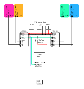
As an MCU we used Arduino Micro. Then we added some bypass capacitors (2x 100n, 10u) to filter out unwanted broom and some pull-up resistors on bus wires just to be sure. The I2C address of a ADC board is set using ADDR pins, one is connected to GND (I2C addr: 0x48), one to VDD (0x49). The whole electronics is soldered on a development board which was cut to fit in the box.


2.2. box & front panels
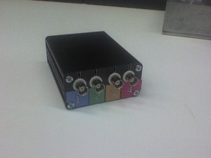
We have used 100x81x40 mm aluminum box from RS online. There had to be made holes for BNC and USB connectors. Because of some development reasons we had there are some slots for wires that connect BNC connectors to the board. Next time I’d recommend to connect BNC to board using some disconnect-able pins.
I’m not going to add any schematics of a front and rear panels because position of holes might differ in your case – it is dependent on how you place your arduino on board and which height you put your board in.

2.3. software
If using Arduino, you would like to use wire library for controlling I2C bus. More conveniently, there is a library by Adafruit which encloses the I2C fiddling into few commands. There were some flaws little that are good to know about:
a) The lib was written for ADS1105 but happened to work for ADS1115. So some variables/macros are non-intuitively labeled.
b) The waiting for conversion was inappropriately long for given SPS.
c) ADS1115 class uses some ADS1105 macros, for example the mentioned ADS1115_CONVERSIONDELAY.
That’s why is the slightly modified lib also in specs and manuals folder, link is in section 1.4.
3. Resources, references, links


Po stěhování na Copy složka se soubory:
https://copy.com/tWYLrRSNpEsox1Rx
Hi Robert, congratulations on your work.
I am very interested to replicate your project,, but the files aren’t disposal because the copy.com service web is no longer available.
can send you, to my a copy the files to my mail?
thanks very much
welcom
Hello,
I have refreshed links in the article to the new cloud destination. Check this Dropbox folder: https://www.dropbox.com/sh/lsmakjqht1c2ert/AAAqZagNicd6dPR5iEwdPkEoa?dl=0
Thanks for your interest,
Robert
Hello!
One correction, you wrote: “One limit is on maximal allowed voltage – with gain 2/3 device can not handle more than +/-6.144V.”
That is not true. From the datasheet: “This parameter expresses the full-scale range of the ADC scaling. In no event should more than VDD + 0.3V be applied to this device.”
True, thank Igor. Blogpost updated.
Pingback:Using the Arduino UNO as a basic DAQ | Arduino based underwater sensors